We continue to make positive progress in the technical program, albeit with some challenges that have needed to be overcome. The major success that we had was in relation to the testing of our recuperator which is reported in more detail below.
In general, and as has been reported in previous newsletters, COVID-19 has impacted the supply chain associated with the fabrication of some of our prototype components. The testing of several of these components is critical to being able to freeze the design of the individual component in order to proceed to whole engine design and analysis, and ultimately to prototyping.
The Recuperator
The most important and technically challenging component of our engine – the recuperator – is one such item. The performance of the recuperator will drive the performance and consequent design of the downstream components such as the combustor, guide vanes and turbines, while the performance of the turbines will then drive the final design of the upstream components such as the compressor. Consequently, it is critical to establish the performance of the recuperator in order to be able to finalise and freeze the design of the remaining components.
Many of you are likely aware of the acronyms DFM and DFAM which stand for Design for Manufacturability and Design for Additive Manufacturing. Our initial recuperator was designed based on advice that we had received from an additive manufacturing (AM) company that we had engaged with for prototyping of the recuperator test pieces. Subsequent advice from that AM company resulted in the need for several iterations of redesign of our recuperator to facilitate the ability to additive manufacture it.
Considerations such as printing to strict dimensional tolerances, wall thickness limitations, surface finish within the microchannels, support structures required during printing, stress relief following printing to prevent deformation, the ability to remove all powder from the microchannels following the printing process, etc were all considerations that needed to be addressed. Trial prints of small test pieces were conducted which resulted in further design changes. The final version of the recuperator design that was sent for printing was our R3-V3 (Revision 3-Version 3), design and this was undertaken during late November 2020.
Between October and December 2020, our engineers fabricated the recuperator test rig. Delays were experienced in assembling and commissioning the test rig. This meant that the recuperator testing that had been scheduled to be undertaken during October was finally undertaken during mid to late December 2020.
The aim of this series of testing of the recuperator was to be able to determine a correlation between the theoretical predicted performance and the actual performance of the recuperator. Of significant importance was to accurately measure hot and cold gas pressure losses, as well as the heat exchange capabilities of the recuperator. Overall performance is dependent on both the effectiveness and pressure losses of the recuperator.
We are very pleased to advise that the results of the testing have given us the tools to be able to more accurately predict the performance of the recuperators that we design, and we now have a good indication as to how our R3-V3 version of our recuperator will perform. The results of our testing of R3-V3 have enabled us to complete the design and analysis of the recuperator that will be installed in our prototype engine.
Now that we are able to more accurately predict the performance of our recuperator and have a more accurate guide to the cost of manufacturing it using the AM process, as well as determining an accurate weight for it, we have been able to undertake a cost/benefit analysis to determine the final configuration of the recuperator. It is anticipated that at 10,000’, the BSFC will be fairly constant at 0.57 lbs/hp/hr in the cruise power range of 150-180hp. Consequently, a 10,000’ 150hp cruise power setting is predicted to yield a fuel flow of around 12.6 USG per hour.
The Combustor Liner
Another extremely pleasing technical milestone achieved during the last quarter was the finalisation of the combustor liner design. Other than the recuperator, the combustor liner is the most technically challenging component of the engine. Controlling the flame within the combustor to ensure that the engine will run properly throughout the entire operating envelope for the engine and under all atmospheric and environmental conditions is a significant challenge. Not only during normal operations of the engine but also during the start sequence for the engine, both on the ground and in the air. Our combustor liner design and analysis are now completed, and the combustor has been integrated with the remaining components in readiness for the complete engine analysis.
The Engine Control Unit
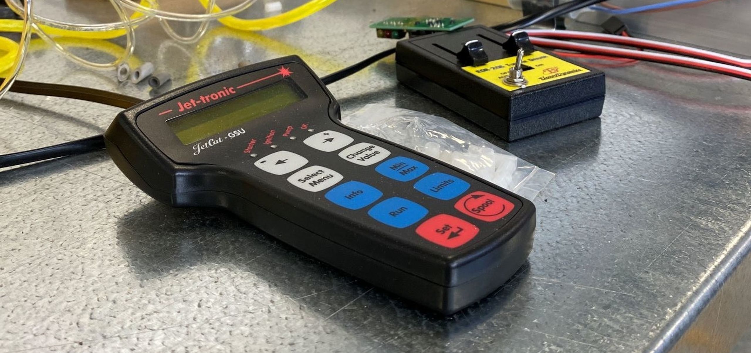
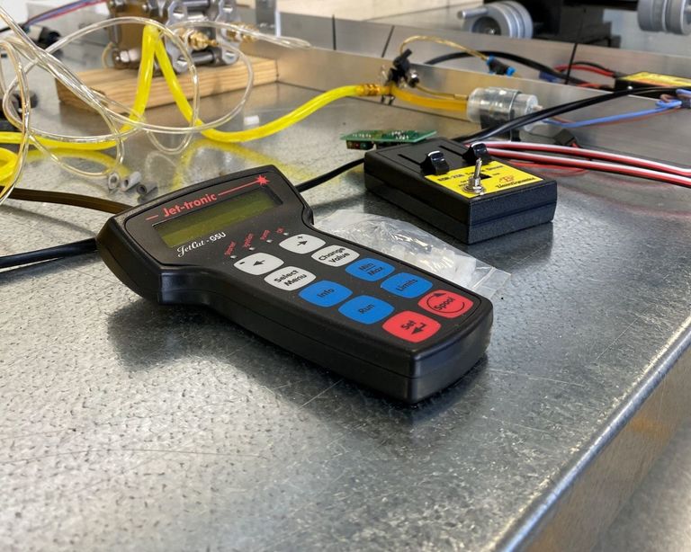
One element of the design process that a nonengineer pilot would find intriguing is that of the development of our engine control unit (ECU). The team who is undertaking this task has designed a system that has been incorporated into a simulator which allows the simulation of start sequences, setting specific power settings, conducting slam accelerations/decelerations, etc. It is fascinating to view the effects of power lever changes to the performance of compressors, turbines, etc, and also how much power is delivered to the propellor and how much fuel is used in these scenarios.
Building the protections into the control system is also fascinating to watch. Of course, our system is being designed to make sure that the pilot should never be able to unintentionally damage the engine or adversely affect its operation. Pilots should not need to worry that the engine will have an overtemperature or overspeed, etc, regardless of what they do with the throttle.
It is important that this is managed electronically and that is what our system will do. It is intended that our engine will have an integrated Power Control Unit (PCU) which will consist of the ECU to control the engine and a Propellor Control Unit to control the constant speed propellor. Our PCU will offer single lever control for the engine/propellor to simplify the operation of the engine.
We intend for engine operation to be as simple as possible. Our customers should be able to turn the engine master on and press the start button to start the engine. Once started, throttle forward more power, throttle back less power. Engine master off to shut down the engine.
Who wouldn’t want a turbine that has these features?
Interested to learn more about our technical program? You can read more useful tips, articles and posts by checking out our Resources section where we've detailed the four stages of developing our turboprop engines.
To stay up to date with our technical program updates, please subscribe to our newsletter using the button below.


